AVR programming - hardware and software requirements

Note: This is NOT a page on how to write (create) software for the Atmel AVR microcontrollers, there are pages all over the web for that (Google "avrfreaks" for a good starting point). Rather, this page is intended for experienced technicians, showing what is needed for uploading data to a new design, or for updating existing firmware.
This is written for people experienced with electronics and computers, specifically Windows XP and Windows 7.
Links to sources are provided at the bottom of the page. Check these for latest versions and for further information.
First, a programmer is needed to connect the AVR to a USB port. An open source design called a USBAsp is used here, these are open source and cheap / easy to obtain.
Buy one from eBay: Under $5, posted free to almost anywhere in the world. Lots of sellers, but we recommend this seller as he sticks to the hardware design and has sold lots of them to people we know without any issues. At this price, it's not worth making them yourself.
Driver and application files you'll need. Right click on "Download File" and "Save target as" (Internet Explorer) / "Save link as" (Firefox) to save them to your computer.
Instructions:
| avr_firmware_uploading.pdf |
Drivers for Windows (2000 to Win7):
| usbasp_-_windows_drivers.zip |
Application:
| usbasp_-_extavr12.zip |
| m32-x12a.hex |
| m32-x12a.pdf |
| bcd_hwa6.hex |
| bcd_hwa6.txt |
| bcd_hwa6.jpg |
| i2c_all.txt |
| i2c_all.hex |
| alt_disp.hex |
| enc_lib_test.hex |
| madison_100_text.txt |
| madison_100_hex.hex |
| lc_pll_portc.hex |
| lc_pll_portc.txt |
| portc_change_1.jpg |
The m32-x12a files are test files for verifying that Extreme, USBAsp, and Mega32 AVR chips are all talking to each other.
It flashes 2 LEDs connected to pins 20 and 21 of the AVR - the .pdf is a document showing the steps and fuse settings, and the .hex is the actual test code.
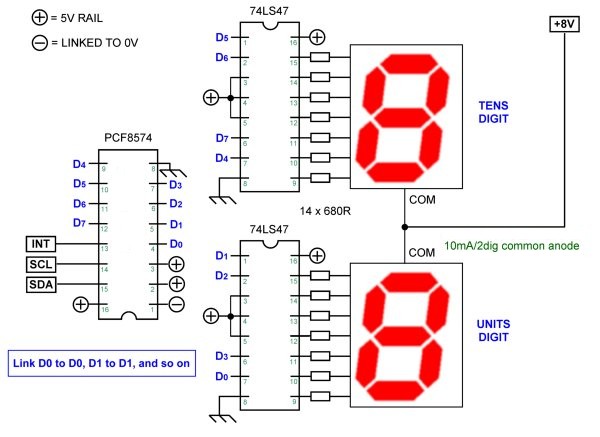
The files that start with "BCD" are for a test routine that is used to display a two digit number onto a pair of 7 segment LED displays via BCD decoder ICs.
See the text and jpg for details. The first one is the hex file that contains the compiled code.
The files that start with "i2C_all" put the radio onto a single channel to test if all the I2C comms is working correctly.
The last one is the hex file that contains the compiled code:
Chan display = "19"
Freq display = "27185"
PLL to N=82 (27.185 Mhz if using an 11.1758 Mhz downmix crystal)
If this works correctly then the I2C outputs are completed, and only the inputs to go...
The hex file Alt_Disp.hex is identical, except it uses the alternate address version (PCF8574A) for the frequency display only. This us untested (because I don't have any "A" suffix devices - try / use at your own risk!
The hex file Enc_Lib_Test.hex is a two in one test - lib and encoder. The lib is for the "A" alternate address version of the output port chip.
The encoder is temporarily connected to pins 39 (PA1) and 38 (PA2) for this test. Other inputs may be connected, they will just be ignored.
It should, if all goes well, perform selection of 1 to 40, sending the correct (hopefully!) data to the PLL, channel, and frequency ports - just like a standard radio!
The PLL is coded for an 11.175x crystal, if you use the standard "325" you will be 450Khz off frequency :-)
The Madison_100 files are version 1.00, done semi-blind due to lack of components here. The text file contains wiring and other connection details, and the hex file is the data that needs to be uploaded to the AVR. As soon as someone with "A" chips confirms it working, I'll tidy up this page :-)
Madison update: A suspected bus capacitance issue caused the port at HWA#7 to fail, so it was reworked to be driven from port C of the AVR.
The text file LC_PLL_PortC.txt contains fuse setting details, and the hex file LC_PLL_PortC.hex is the data that needs to be uploaded to the AVR
The fuse setting is important - by default the pins are a JTAG port and the fuse needs to be changed to tell the AVR to use these pins as a regular port.
References and links (check these for latest versions and lots more info, such as schematics on AVR interfacing):
Make your own from the USBAsp site http://www.fischl.de/usbasp/ if you want to know how these things work.
Far cheaper to buy them on eBay than making your own though!
Extreme Electronics :Extreme burner AVR application and programming tutorials
Below is an experimental conversion from C to MCS, use at your own risk. It's a "roger beep", single tone, using an ATTiny45.
It flashes 2 LEDs connected to pins 20 and 21 of the AVR - the .pdf is a document showing the steps and fuse settings, and the .hex is the actual test code.
The files that start with "BCD" are for a test routine that is used to display a two digit number onto a pair of 7 segment LED displays via BCD decoder ICs.
See the text and jpg for details. The first one is the hex file that contains the compiled code.
The files that start with "i2C_all" put the radio onto a single channel to test if all the I2C comms is working correctly.
The last one is the hex file that contains the compiled code:
Chan display = "19"
Freq display = "27185"
PLL to N=82 (27.185 Mhz if using an 11.1758 Mhz downmix crystal)
If this works correctly then the I2C outputs are completed, and only the inputs to go...
The hex file Alt_Disp.hex is identical, except it uses the alternate address version (PCF8574A) for the frequency display only. This us untested (because I don't have any "A" suffix devices - try / use at your own risk!
The hex file Enc_Lib_Test.hex is a two in one test - lib and encoder. The lib is for the "A" alternate address version of the output port chip.
The encoder is temporarily connected to pins 39 (PA1) and 38 (PA2) for this test. Other inputs may be connected, they will just be ignored.
It should, if all goes well, perform selection of 1 to 40, sending the correct (hopefully!) data to the PLL, channel, and frequency ports - just like a standard radio!
The PLL is coded for an 11.175x crystal, if you use the standard "325" you will be 450Khz off frequency :-)
The Madison_100 files are version 1.00, done semi-blind due to lack of components here. The text file contains wiring and other connection details, and the hex file is the data that needs to be uploaded to the AVR. As soon as someone with "A" chips confirms it working, I'll tidy up this page :-)
Madison update: A suspected bus capacitance issue caused the port at HWA#7 to fail, so it was reworked to be driven from port C of the AVR.
The text file LC_PLL_PortC.txt contains fuse setting details, and the hex file LC_PLL_PortC.hex is the data that needs to be uploaded to the AVR
The fuse setting is important - by default the pins are a JTAG port and the fuse needs to be changed to tell the AVR to use these pins as a regular port.
References and links (check these for latest versions and lots more info, such as schematics on AVR interfacing):
Make your own from the USBAsp site http://www.fischl.de/usbasp/ if you want to know how these things work.
Far cheaper to buy them on eBay than making your own though!
Extreme Electronics :Extreme burner AVR application and programming tutorials
Below is an experimental conversion from C to MCS, use at your own risk. It's a "roger beep", single tone, using an ATTiny45.
| unibeep_12.bas |
Another version of it,identical but instead of a beep, it plays "Dixie" from the musical horn of the "General Lee" Hazzard car.
| dixiebeep.bas |
Below is a useful addition to the Cobra 2000 base. This turns the tone control into a general coverage VFO. Note: if you want to retain the ability to switch between VFO and channel modes, you'll need to add 6 diodes (1N914, 1N4148, or BAW62 will do) between the channel selector and the PLL.
The encoder is a common 90 degree 24 pulse/rev unit that can be had on eBay for a few dollars.
The first file is the schematic.
The second is the hex file (for those folks without the compiler).
The third file is the source code (for those with the MCS AVR compiler installed). Compile, upload, and enjoy...
The fourth file is for troubleshooting. This is an update on the earlier LED test routine, this one also tests the input signal on pin 14 is being received.
When the radio is switched to channel mode, the LED will flash approximately 3 times per second.
When the radio is switched to VFO mode, the LED will flash approximately once per second.
Use it to verify comms and fuse settings are OK and that port B (input) is working correctly, if things don't go quite as expected.
NOTE 1: Don't forget to re-compile before uploading a new version!
NOTE 2: Pin 14 should never go above 5V. If it does, you definitely have a dead diode and probably a dead micro, too...
| c2k_vfo_102.jpg |
| c2k_vfo_102.hex |
| c2k_vfo_102.bas |
| c2k_ledtest.bas |
