Project #1 - Universal sequencer
This is only for radios that have a constant read frequency counter fitted. It uses a rotary encoder to cover the whole band with no gaps using a single control, VFO style. It can be made switchable between channel and VFO by using a couple of tristate ICs such as 244/245/573 to isolate the 8 bits from the switch when in VFO mode.
| mega8_to_858_rev2.pdf |
| programming_the_sequencer.pdf |
| seq_100.eep |
| seq_100.hex |
| test_100.eep |
| test_100.hex |
Project #2 - Binary (i.e. Superstar) switch adapter
This enables the use of a common binary replacement (i.e. SS3900) switch to replace a worn out 40 year old original:
This enables the use of a common binary replacement (i.e. SS3900) switch to replace a worn out 40 year old original:
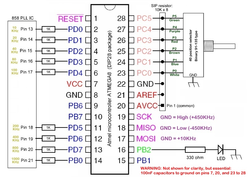
The replacement switch must have originally had binary N-codes of 91 to 135.
It's wired differently to suit the above circuit (inverted with the common connected to ground and pullup resistors, and the P6 / P7 wires are not connected.
Not sure of the fuse setting yet, I'll update this page with the details in the next few days when we've worked out what works best in the radio.
Files below:
EXT142 - The programming utility used to load the hex files into the Mega8 IC. Used with the USBAsp programming adapter. WinXP or Win7 only.
Bin858_LED - Hex file for the LED test (load this one first to make sure the fuse settings are correct, the LED will blink at a 1Hz rate if it's correct.
Bin858_100 - Hex file for the above circuit. Only upload this when the LED program above has been verified to work as stated!
If all goes well, the radio will have the standard 40 channels with pins 17 / 18 / 19 open. The LED should briefly flash on channel change.
Ground pin 17 for +10Khz, pin 18 for low band, and pin 19 for high band.
Pins 17+18 and pins 17+19 can be used to fill the gaps on the other bands, but grounding pins 18+19 will move it up and down by 450KHz at the same time, in other words back on the FCC channels...
Files for project #2:
| ext142.zip |
| bin858_led.hex |
| bin858_100.hex |
